Chronological Build |
|
|
3/6/04 -- Disassembly Continues -- Some Assembly Begins While we're continuing to dismantle portions of the car, this installment of the Chronological Build will focus mostly on installation of the motor and transaxle. It is pretty easy with the right support equipment...and the appropriate process. |
|
|
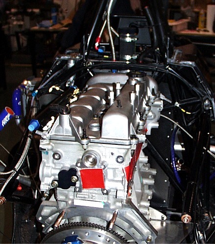
STEP 1: Prepare the Motor Prior to installing the motor here's what we recommend you do:
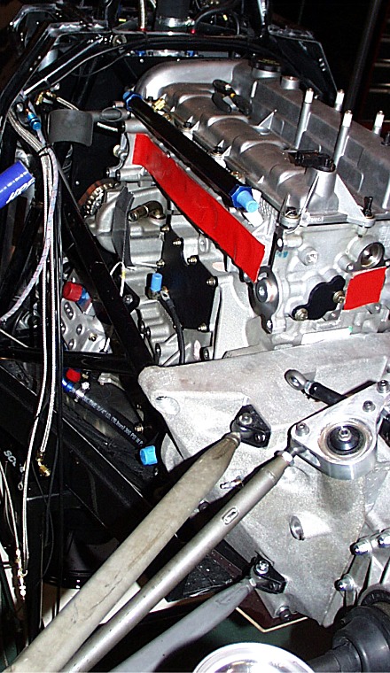
a) Mount the front motor plate. Here you can see
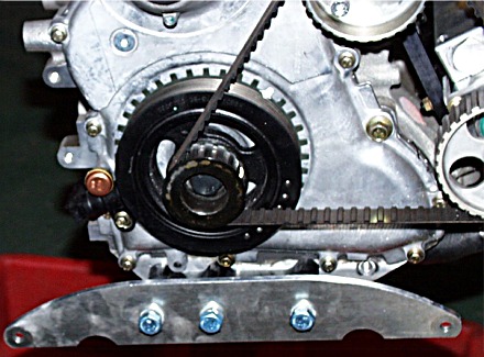
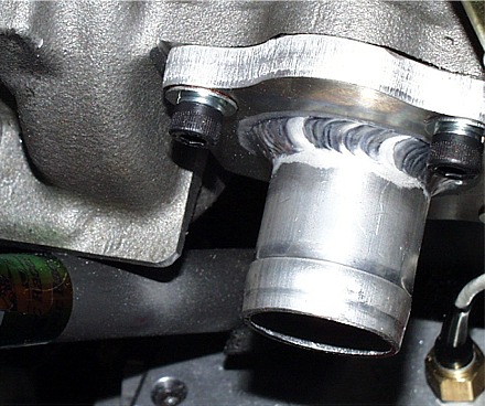
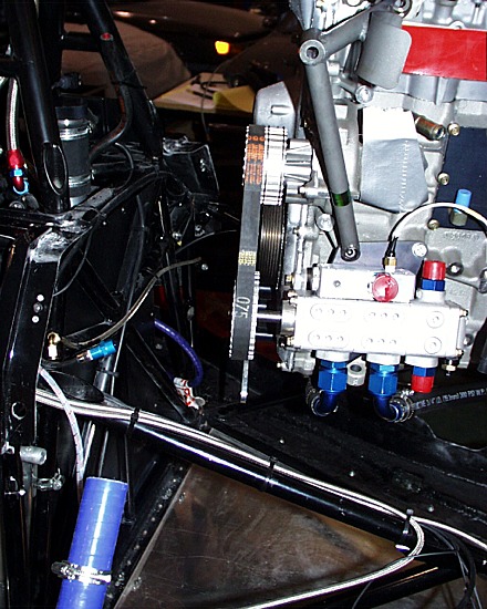
c) Now is a good time to do some other prep work such as knocking down sharp edges and installing the alternator belt. Naturally, I forgot to do both. But to illustrate, here's a particularly nasty bit. The edge on the water pump is quite sharp...you can see it here with the motor installed.
Here you see the same corner after I cleaned up the blood and rounded the corner off. If the motor weren't installed at this point, I'd be more aggressive in the removal of this and other little built-in "razors".
STEP 2: Remove the Transaxle OK, now it's time to pull the transaxle off the end of the chassis. You'll see that one of the key concepts in making for a painless engine installation is the creation of a transaxle cart. This cart has a basic height that mates up with your car cart...and the transaxle cart has height adjusters that let you raise, lower and tilt the transaxle to align it to the car and engine. I'll be posting more detailed instructions on how to make this cart at a future time. Big thanks go out to John Church at JDC Motorsports for the design concept.
And now we slip the transaxle cart itself under the car and start bolting the cart to the adapter above and the transaxle.
So here's the transaxle cart fully bolted up to the transaxle prior to removal. Look closely at the lower left corner of the picture and you can see one of the 4 height adjusters on the upper frame of the transaxle cart. Looking at the bottom of the picture, you can also see the locking casters on the lower frame of the cart. Both of these features are important for ease of use.
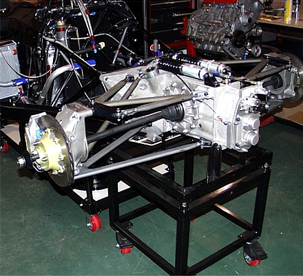
This is a good overall shot of how the transaxle cart relates to the car cart and the car.
Now we've removed the bolts holding the transaxle to the chassis and pulled the transaxle away from the frame.
With the transaxle removed from the chassis, now is a good time to remove the rear sway bar. Here you see the transaxle with the sway bar gone. Also, this is the time to remove the alignment dowels from the transaxle (you should keep the set in the motor) and check the throw-out bearing fittings for tightness. I also think it's a good idea to LIGHTLY coat the face of the throw-out bearing with a little grease and put some anti-sieze on the input shaft of the transaxle. OK, update from 2007....Steve Fox from PTT has convinced me that we should NOT put any anti-sieze on the input shaft. Leave it dry. Anti-sieze will only slow down the action of the clutch. The anti-sieze thing was as hold over from my in/out box midget days.
Here we're looking at the empty engine bay. There are a two things you should do right now. 1) Remove the left and right upper motor mounts. 2) Position any wiring running on the bulkhead tubes to be as close to the fuel cell skin as possible (i.e. rotate the starter power wire off the face of the lower left bulkhead tube. Also notice Robert installing the data acquisition system on the cockpit floor.
STEP 3: Install the Motor
Now we've got the motor hanging on a crane and have it positioned ready to lower into the engine bay. Note that we've got the LF motor mount LOOSELY connected to the motor via the lower bolt only.
We then lower the motor to the floor of the car and bolt the front motor plate to the chassis. The motor plate should rest on the piece of steel angle at the lower edge of the rear bulkhead. We also make a change to one of the supplied fasteners. On the LEFT side of the car, we use a hex head bolt in lieu of the supplied socket head part. The reason for this is the ease of getting a ratchet in this location. On the right side of the car, we leave the socket head bolt because it's quite open on the right side and easy to tighten the bolt with a hex ball driver. BTW, the required hex head bolt is an 8mm x 1.25 x 50mm part.
STEP 4: Install the Transaxle
Now it's time to bring the transaxle back and mate it up with the engine. Here you see the transaxle cart in position and the transaxle started on the motor studs. Wiggling a brake disk will help line up the splines on the clutch disk and the transaxle input shaft. The motor is sitting with the rear of the oil pan sitting on the floor of the car (in other words the motor is tipped down at the back). So a combination of adjustment of the transaxle stand angles (with the 4 levelers in the stand) and pry bars placed under the rear of the motor will help you get things lined up. One big thing we learning is that the upper chassis frame rails have a considerable "spring" to them. To install them in the transaxle you need to push on them to line them up...not hard and it shouldn't require anything more than a healthy push of your hand.
Install the transaxle-to-engine and transaxle-to-chassis bolts as you can and gently draw up the transaxle to the engine. Then it's time to install the left and right front motor mounts. Note that you should have the LF mount loosely attached to the oil pump plate at this time. We found that loosely installing the LF motor mount (install the 2 engine bolts first, and then the frame bolt) and then installing the RF motor mount (also install the 2 engine bolts first).
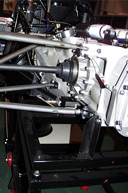
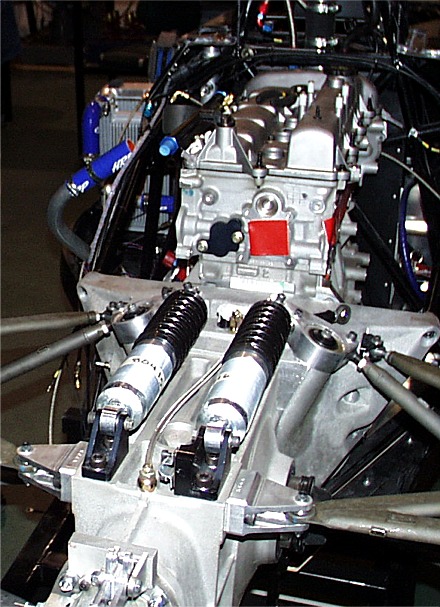
And finally, here we have a shot of the installed engine/transaxle.
More to come in the next day or so! |
|
| Rev. 1/22/08 | |
| Feedback | |
| I welcome your
comments or ideas on this information. Feel free to drop me a line via
“Comments and Feedback”. Barry Mumm |
|
 it mounted
to our motor. You can also see that we changed the front mounting
bolts from socket head cap screws to hex head. We've found that if
you leave the front motor plate slightly loose, it really helps when
lining up the motor plate to frame bolts. It's very difficult to
tighten the socket head bolts when the motor is in place, so we
substituted 10mm - 1.5 x 80 mm hex head bolts for the original items...and
now you can tighten up the front plate after the motor is fully installed.
it mounted
to our motor. You can also see that we changed the front mounting
bolts from socket head cap screws to hex head. We've found that if
you leave the front motor plate slightly loose, it really helps when
lining up the motor plate to frame bolts. It's very difficult to
tighten the socket head bolts when the motor is in place, so we
substituted 10mm - 1.5 x 80 mm hex head bolts for the original items...and
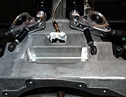
now you can tighten up the front plate after the motor is fully installed. 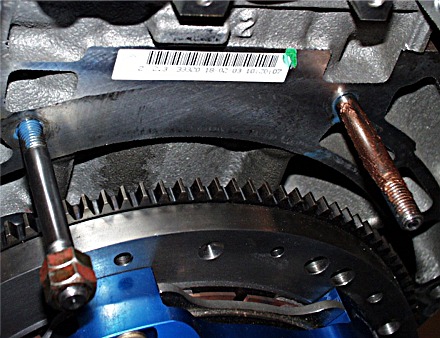 b) Next, install the studs on the rear top of the motor.
Here you can see the studs installed. I want to make two
observations. First, note that the right stud is coated with anti-sieze,
a good idea when two different metals are in close contact and can get
wet. Also, on the left stud, you'll see that we're about to tighten
it down and you can see the blue Loctite we used to retain the stud.
b) Next, install the studs on the rear top of the motor.
Here you can see the studs installed. I want to make two
observations. First, note that the right stud is coated with anti-sieze,
a good idea when two different metals are in close contact and can get
wet. Also, on the left stud, you'll see that we're about to tighten
it down and you can see the blue Loctite we used to retain the stud.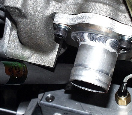
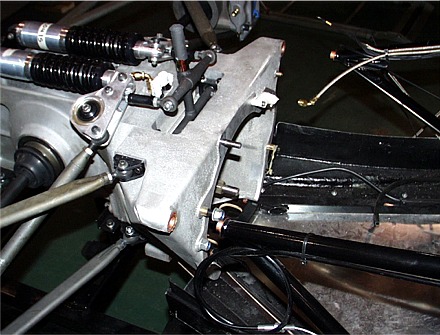
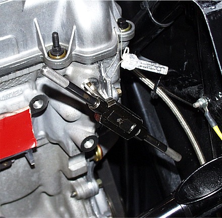
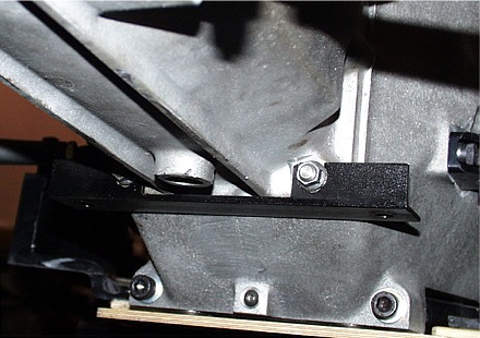 So,
here we've installed an adapter that mates the front of the transaxle to
the cart. As you can see, it's a pretty simple piece.
So,
here we've installed an adapter that mates the front of the transaxle to
the cart. As you can see, it's a pretty simple piece.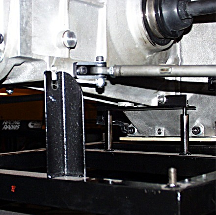
 You'll
also note that the motor mounts also have some "spring" to them and may
require creative use of a pry bar to install them. The most important
thing is to remember that you're trying to thread steel bolts into an
aluminum motor...and you have to be careful. The picture at right is
of my having to clean up the threads on the right side of the head because I
was impatient with the line-up. Don't let this happen to you.
You'll
also note that the motor mounts also have some "spring" to them and may
require creative use of a pry bar to install them. The most important
thing is to remember that you're trying to thread steel bolts into an
aluminum motor...and you have to be careful. The picture at right is
of my having to clean up the threads on the right side of the head because I
was impatient with the line-up. Don't let this happen to you.