Clutch Alignment Tool |
|
| Background | |
| When changing motors or changing the clutch, alignment of the clutch disk, pilot bearing (in the crankshaft) and transmission input shaft is critical for easy installation. Without a clutch alignment tool, it can be very difficult to get the disk properly centered and hard to actually install the clutch itself. With the tool described below, you are insured alignment and it makes installing the clutch to the flywheel a snap. | |
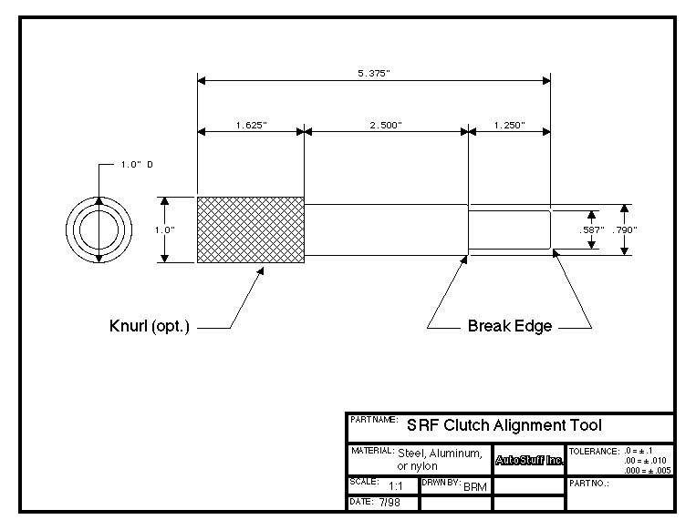
| The Clutch Alignment Tool | |
| The clutch
alignment tool show in the drawing below is the ticket. Click on the
“thumbnail” picture to get a full size drawing to print.
|
|
| Construction
Notes I made my tool from a 1" diameter piece of mild steel rod. You could use almost any machinable material...aluminum or plastic would work fine. I used steel for long life. The down side of building this tool is that you will need someone with a lathe to make it. But I built mine in about 15 minutes of machine time, so it shouldn’t be too pricey. Knurling the
end of the tool is a nice touch and makes the tool easier to hold. If you make the
tool from steel, you should consider “blackening” the tool with some of the
available concoctions to prevent rusting. Using the tool |
|
| Feedback Request | |
| This is my first time exporting a CAD drawing from my Mac-based CAD system to the web. Please let me know if you can read it and print it. I’ve got a LOT more CAD drawings you might find interesting (chassis dimensions, suspension pick-up point locations, component dimensions, motor and tranny stand plans, etc., etc.). I’ll put them up on this site if the drawings are readable. Let me know. Thanks, Barry. | |
Rev. 7/4/98 |
|