EVD Transaxle Info |
|
|
What we know so far (or at least think we know). We've run our first race on the transaxle and everything worked well. I had a lot of time in the prep of the transaxle, so I'm hopeful this helped. What follows below are mostly pictures documenting various aspects of the EVD transaxle. |
|
| We
decided to dismantle the gearbox prior to our first on track experience.
What follows is photos of the gearbox disassembly.
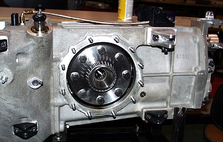
After removing the transaxle from the car we started dismantling. Here we've removed the side plate and you can see the differential still sitting in the housing.
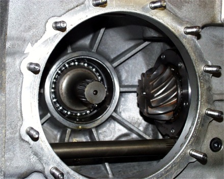
For documentation purposes, here's what the inside of the main case looks like. You can see the right side stub axle (in the center of the picture), the pinion (on the right) and the input shaft (the lower shaft in the picture). Etched on the nose of the pinion, is the recommended pinion depth.
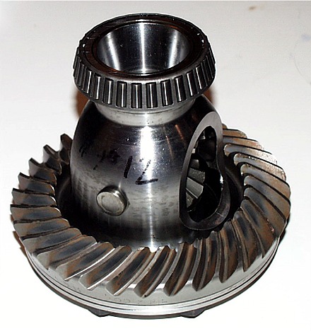
Here's a picture of the differential removed from the case. This is is before we worked on the diff. What we did was:
1) Lapped in the spider gears Note that the backlash setting is etched on the edge of the ring gear.
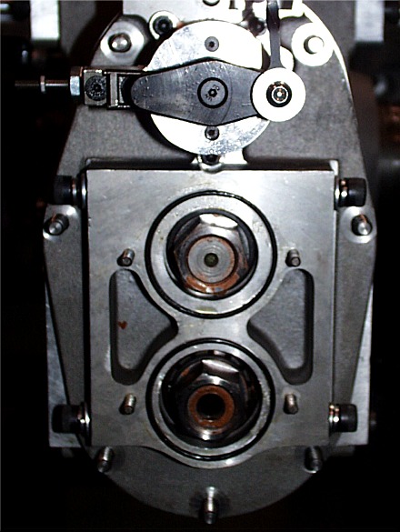
A quick look inside the bell housing. Unfortunately, we have to pull the bell housing/transaxle to get the transaxle off the car. You can see the bolts inside the bell housing.
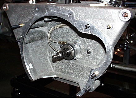
Here's the front of the transaxle after the bell housing has been removed. While it didn't make too much sense to me, I put plenty of silicone sealer on the transaxle flange. The cavity shown here serves as the oil breather "catch can" and you don't want it to leak...even if it's just a little oil.
Removing the rear cover. First put the transaxle into "lock-up"
mode...where both reverse and 5th gear are engaged simultaneously.
Shift into reverse and then pull the reverse lock-out lever and shift into
reverse a 2nd time. This locks the transaxle so you can loosen the
pinion shaft and lay shaft nuts. Note that the pinion shaft (top shaft)
is a LEFT HAND THREAD. Loosen both nuts a bit at a time. Do not
remove the lay shaft (lower) nut completely. Leave it on
"finger-tight". Remove the pinion shaft nut completely. Remove
the cover mounting nuts and start pulling the cover away from the main case
along with the entire gear stack. Although I didn't do it (and ended
up with a bunch of gears in my hands), you can simultaneously
insert a pinion shaft simulator while you're pulling the rear cover and lay shaft out. This will leave you with a complete setup
and not "raining gears".
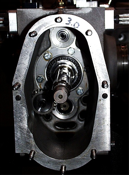
Again, just for documentation, here's the inside of the rear of the main case. You can see the reverse gear idler on the lower left and the pinion shaft top center. I'm not sure what the "3.0" means written on the case...but I'm sure someone does.
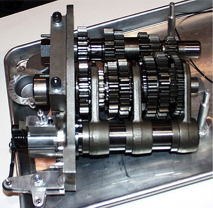
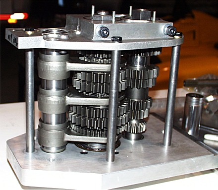
Here you can see the gear stack removed from the car. These shift forks are the "forged forks" which replaced the original machined billet steel pieces.
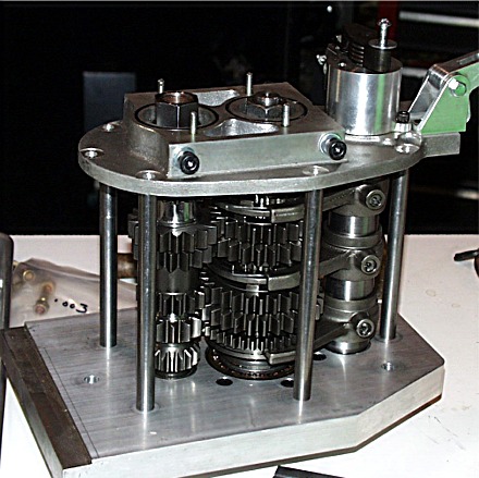
This is the gear stack mounted on a fork setup fixture. This is really an invaluable item for setting up the gear box. The next picture shows the other side of the gear stack on the fixture.
The flip side of the gear stack on the fixture. This fixture lets you set both the fork spacing and the gear centering. It really helped us.
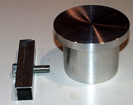
Here's a picture of the pinion depth gauge I made. This item simulates the ring gear. While the design is dirt simple, machining it accurately took some time. The minor diameter fits in the bearing pocket on the right side of the main case. The major diameter simulates the ring gear itself. The final cuts on this tool were about .001" at a time and I spent about 10 minutes between cuts letting the part cool to ambient temperature.
Experience of the First Setup I created a couple crude sketches of the assembly of the gear train to aid my memory when I worked on the gear box.. I'll post them the next time I update this page. |
|
| Rev. 5/10//04 | |
| Feedback | |
| I welcome your
comments or ideas on this information. Feel free to drop me a line via
“Comments and Feedback”. Barry Mumm |
|