Motor
Mounts
It may be hard to believe, but we’ve spent a lot of time on motor
mounts. The reason is that we want to eliminate all the stock
vibration isolation to better get the power to the ground....and to reduce
weight.
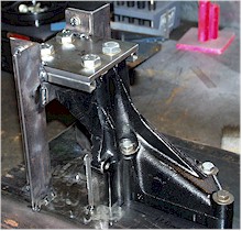 This
is the upper motor mount attached to a jig. It mounts to the
engine block between the heads. In addition, it serves as the
power steering mount. There are 2 issues with this mount: 1) The
left hand head must be removed to take the mount out and 2) It weighs a
ton. This
is the upper motor mount attached to a jig. It mounts to the
engine block between the heads. In addition, it serves as the
power steering mount. There are 2 issues with this mount: 1) The
left hand head must be removed to take the mount out and 2) It weighs a
ton.
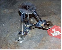
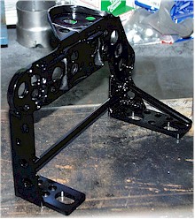
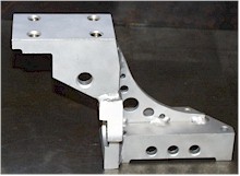 Here
you see the aluminum replacement we’ve developed. This part is
constructed by welding 3 billet pieces together. It reduces the
weight by over half and can be removed and installed without taking off
the heads. Here
you see the aluminum replacement we’ve developed. This part is
constructed by welding 3 billet pieces together. It reduces the
weight by over half and can be removed and installed without taking off
the heads.
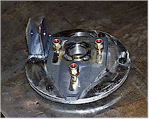
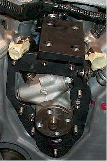 This
is the mount installed on the motor along with an aluminum power steering
mount plate. If you look closely you can see the heads of the
titanium fasteners used to replace the stock parts. The fasteners
alone save 1/2 pound. This
is the mount installed on the motor along with an aluminum power steering
mount plate. If you look closely you can see the heads of the
titanium fasteners used to replace the stock parts. The fasteners
alone save 1/2 pound.
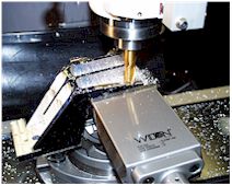 This shot shows the
right front upper
mount being carved out of billet aluminum.
This shot shows the
right front upper
mount being carved out of billet aluminum.
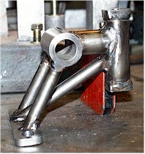
 Here is the mount that bolts to the RF fender and supports the billet
mount above. Shown is the MK2 version and is made from
steel tubing. The MK3 version is on the car now and is
fabricated from 6061 aluminum. Here is the mount that bolts to the RF fender and supports the billet
mount above. Shown is the MK2 version and is made from
steel tubing. The MK3 version is on the car now and is
fabricated from 6061 aluminum.
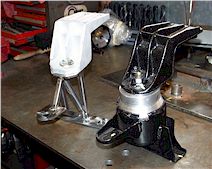 In this shot, you can see the stock upper mount with a MK1 lower mount on the right compared to the billet/tubular
combination on the left. A lot of weight difference here. In this shot, you can see the stock upper mount with a MK1 lower mount on the right compared to the billet/tubular
combination on the left. A lot of weight difference here.
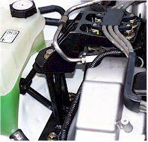
And finally, the MK2 combination installed on the car.

This is the MK1 lower rear xaxle mount that bolts to the
subframe. Note the large aluminum block used to replace the rubber
mount.
 And here you see the tubular replacement. Less than 1/2 the
weight. We’ve built an aluminum version, but it broke during
use...we’re investigating the reason. And here you see the tubular replacement. Less than 1/2 the
weight. We’ve built an aluminum version, but it broke during
use...we’re investigating the reason.
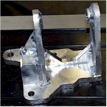
 To
improve access to the transaxle shifter assembly as well as pursue the
holy grail of lighter weight, here’s our modified LF transaxle
mount. We start with the stock part, and end up with this...several
pounds lighter. To
improve access to the transaxle shifter assembly as well as pursue the
holy grail of lighter weight, here’s our modified LF transaxle
mount. We start with the stock part, and end up with this...several
pounds lighter.
 This
is a sample of what we've done for all the cast motor and transaxle
mounts. This part is made from welded billet aluminum
subassemblies. This
is a sample of what we've done for all the cast motor and transaxle
mounts. This part is made from welded billet aluminum
subassemblies.
Steering and Suspension
Our objectives here are to reduce weight, increase rigidity and
provide adjustability.
 This is a close-up of the
MK1 steering rack/tie rod interface. Notice the spherical
rod ends installed in the rack. In the current version, we've reversed
the positions of the rod end and clevis, attaching the clevis to the
rack. This provides more clearance for movement. This is a close-up of the
MK1 steering rack/tie rod interface. Notice the spherical
rod ends installed in the rack. In the current version, we've reversed
the positions of the rod end and clevis, attaching the clevis to the
rack. This provides more clearance for movement.
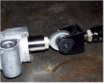
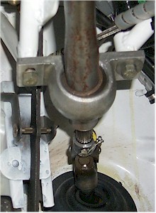
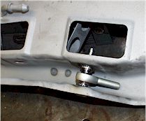
 This
is a close-up of the steering rack interface. At the bottom is a
portion of the stock connector. Normally, it mounts with another
vibration isolating rubber part. We eliminated that and welded a
tube and U-joint to it. The U-joint connects to the lower portion of
the Woodward collapsible steering shaft shown in the picture below. This
is a close-up of the steering rack interface. At the bottom is a
portion of the stock connector. Normally, it mounts with another
vibration isolating rubber part. We eliminated that and welded a
tube and U-joint to it. The U-joint connects to the lower portion of
the Woodward collapsible steering shaft shown in the picture below.
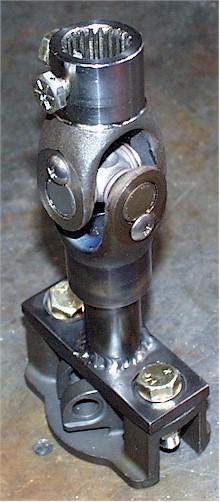
 Here’s
the U-joint thru the firewall connected to the collapsible steering
shaft. You can also see the pillow block that supports the shaft. Here’s
the U-joint thru the firewall connected to the collapsible steering
shaft. You can also see the pillow block that supports the shaft.
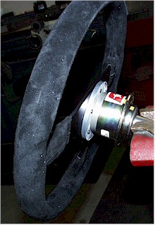 Here’s
the Momo steering wheel mounted to a Sweet quick release hub. We
chose the Sweet release because it’s splined, eliminating slop in the
steering. Here’s
the Momo steering wheel mounted to a Sweet quick release hub. We
chose the Sweet release because it’s splined, eliminating slop in the
steering.
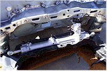 Here’s a shot of the rack mounted to the subframe in the car. Here’s a shot of the rack mounted to the subframe in the car.
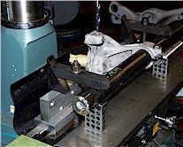
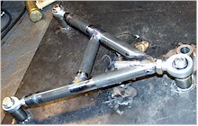 This
is the MK2 front lower control arm being held on its fabrication jig. We make this part out of 4130 chrome-moly
tube. There are National spherical bearings for the subframe mounts
(replacing the stock rubber bushings) and one for the connection to the
steering knuckle (replacing the stock lower ball joint). The MK3
version of the LCA features new outer rod end alignment to allow for pure
camber adjustment. This
is the MK2 front lower control arm being held on its fabrication jig. We make this part out of 4130 chrome-moly
tube. There are National spherical bearings for the subframe mounts
(replacing the stock rubber bushings) and one for the connection to the
steering knuckle (replacing the stock lower ball joint). The MK3
version of the LCA features new outer rod end alignment to allow for pure
camber adjustment.
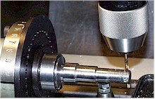 A stud
mounts to the steering knuckle and provides mounting for the large rod
end. Here you can see the LBJ stud being cross-drilled for safety wire.
The stud is made from 4340 steel and heat treated for strength. A stud
mounts to the steering knuckle and provides mounting for the large rod
end. Here you can see the LBJ stud being cross-drilled for safety wire.
The stud is made from 4340 steel and heat treated for strength.
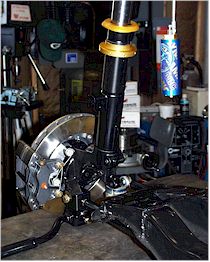
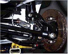
 Here’s
a shot of the MK2 suspension installed on the car. Here’s
a shot of the MK2 suspension installed on the car.
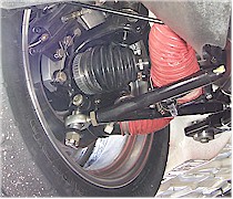
 Turning to the rear suspension, here you can see the right rear suspension with the
remote canister of the shock dangling. Turning to the rear suspension, here you can see the right rear suspension with the
remote canister of the shock dangling.
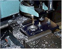
 Here
we�re drilling out one of the rear Quadralink mounts to convert it to
1/2-20 thread so we can use a rod end Here
we�re drilling out one of the rear Quadralink mounts to convert it to
1/2-20 thread so we can use a rod end
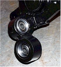 This close-up is of the rear knuckle. As you can see, we’ve replaced the
factory rubber bushings with spherical rod ends. We’ve done this
everywhere. There are no rubber bushings left in the suspension -- anywhere. This close-up is of the rear knuckle. As you can see, we’ve replaced the
factory rubber bushings with spherical rod ends. We’ve done this
everywhere. There are no rubber bushings left in the suspension -- anywhere.
 You can see the tubular steel replacements for the stock, stamped steel transverse
links. You can see the tubular steel replacements for the stock, stamped steel transverse
links.
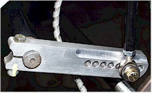 Here’s
a close-up of the rear sway bar arm. We replaced the stock sway bar
with a Schroeder torsion bar. The bar is carried in a tube welded to
the rear subframe. The arm shown connects the bar to the strut --
via the tubular link at the right of the picture. Adjustment is made
by placing the rod end in a different hole in the arm. Here’s
a close-up of the rear sway bar arm. We replaced the stock sway bar
with a Schroeder torsion bar. The bar is carried in a tube welded to
the rear subframe. The arm shown connects the bar to the strut --
via the tubular link at the right of the picture. Adjustment is made
by placing the rod end in a different hole in the arm.
 Here’s a shot of construction of the front and rear camber plates.
Basically a simple job...but time consuming anyway.
Here’s a shot of construction of the front and rear camber plates.
Basically a simple job...but time consuming anyway.
 A finished front camber plate.
Note the bracket for the strut tower bar. This is a MK1 part. We
remade the same design in aluminum for lighter weight. There is a MK3
part being installed for the 2002 season. After we’ve run it, I’ll
provide a picture. A finished front camber plate.
Note the bracket for the strut tower bar. This is a MK1 part. We
remade the same design in aluminum for lighter weight. There is a MK3
part being installed for the 2002 season. After we’ve run it, I’ll
provide a picture.
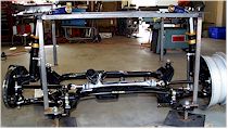 This shows the complete front suspension mounted to a jig we built to simulate the
car’s shock towers. It even has camber plates on it. This shows the complete front suspension mounted to a jig we built to simulate the
car’s shock towers. It even has camber plates on it.
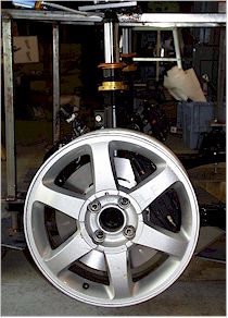 Here’s a side view of the simulator with a stock 16" x 6.5" wheel
mounted to the hub. The 12" diameter rotors fill the wheel nicely. Here’s a side view of the simulator with a stock 16" x 6.5" wheel
mounted to the hub. The 12" diameter rotors fill the wheel nicely.
Brakes
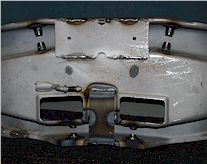
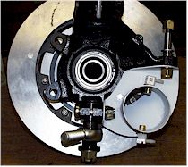 This is a close-up of the back of a front rotor without a caliper installed....but with
the brake air duct on. Notice how the air duct directs the air to the inside of the
rotor. Also note the two water mist nozzles mounted in the duct to provide
evaporative cooling of the rotor. This is a close-up of the back of a front rotor without a caliper installed....but with
the brake air duct on. Notice how the air duct directs the air to the inside of the
rotor. Also note the two water mist nozzles mounted in the duct to provide
evaporative cooling of the rotor.
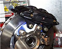 We’re using Wilwood
Superlite III calipers (differential 4 piston design) and Coleman Machine heavy duty
curved vane rotors on the front of the car. On the rear, Wilwood Superlite calipers
(but without the differential piston sizes) and lighter duty Coleman rotors.
These are the MK1 selections. We’re still using the same calipers
but with different rotors. I'll have pictures later. We’re using Wilwood
Superlite III calipers (differential 4 piston design) and Coleman Machine heavy duty
curved vane rotors on the front of the car. On the rear, Wilwood Superlite calipers
(but without the differential piston sizes) and lighter duty Coleman rotors.
These are the MK1 selections. We’re still using the same calipers
but with different rotors. I'll have pictures later.
Subframes
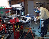 Yours truly
welding up the seams on the front sub-frame. See the closeup below. Yours truly
welding up the seams on the front sub-frame. See the closeup below.
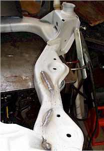
 This
is the latest modification to the front subframe. Here I’ve replaced
the front steel member, with a drilled tubular aluminum part. It saves
a lot of weight. This shot shows the subframe mounted in a jig I built
to simulate the car and radiator mounting. This
is the latest modification to the front subframe. Here I’ve replaced
the front steel member, with a drilled tubular aluminum part. It saves
a lot of weight. This shot shows the subframe mounted in a jig I built
to simulate the car and radiator mounting.
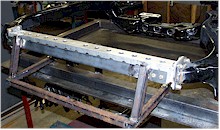
 This shows the type of
modification we’re making to most of the suspension ...converting to rod ends and
spherical bearings. This is a shot of a rear sub-frame with the first of 4 spacer
sets welded in. This shows the type of
modification we’re making to most of the suspension ...converting to rod ends and
spherical bearings. This is a shot of a rear sub-frame with the first of 4 spacer
sets welded in.
 Here you can see a
completed rear sub-frame prior to powder coating. Spacers in place, seams welded and
some added metal to increase the strength and reduce deflection. Here you can see a
completed rear sub-frame prior to powder coating. Spacers in place, seams welded and
some added metal to increase the strength and reduce deflection.
|